Summary
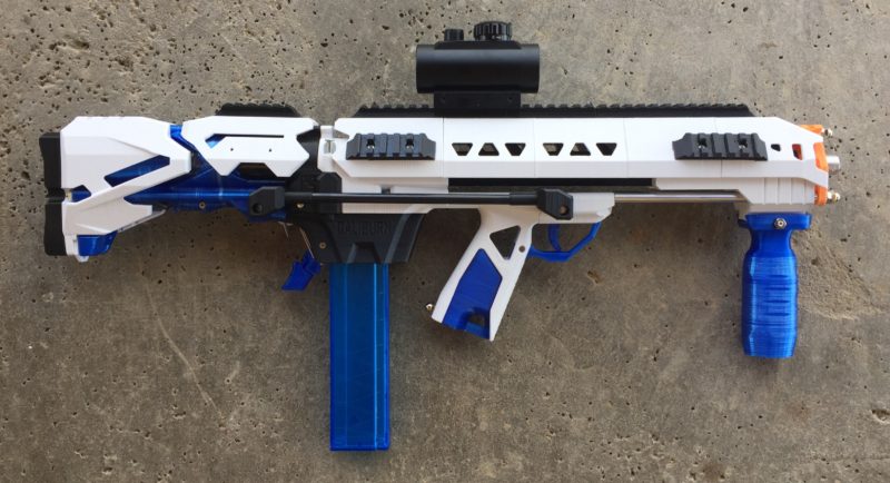
So this page got pretty long lol. I figured I’d add the TLDR section for the casual browser. If you want the full firehose treatment, read on! This page is long, and covers my tinkering of the Caliburn high performance nerf blaster platform in the hopes of creating a viable bull pup variant.
I’m currently working on v0.2; v0.1 was a 3.5″ prime with a 16.5″ length of pull on a 24.5″ total length using a 14″ barrel. Version 0.2 is focusing on reducing the total blaster length by removing 20mm off the plunger tube to help drop the LOP. This version is also focusing on integrating the trigger coupler bars into the magwell for a cleaner look.
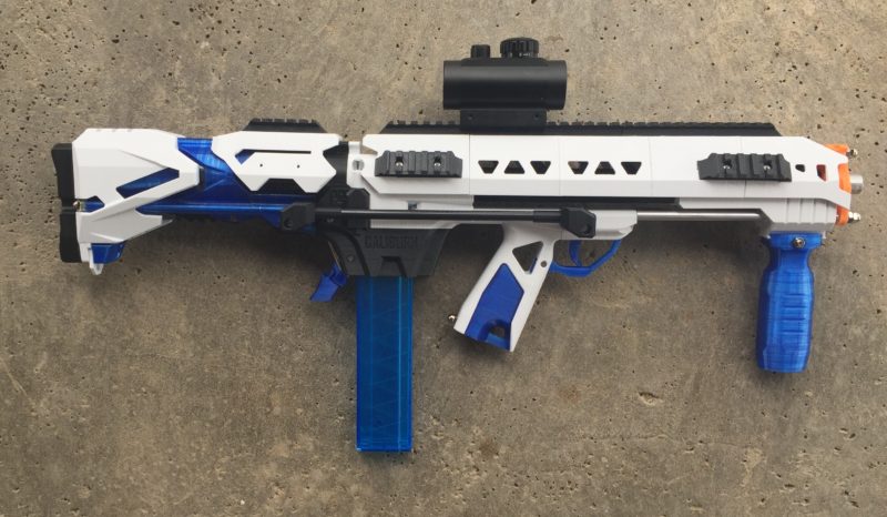
Version 0.1:
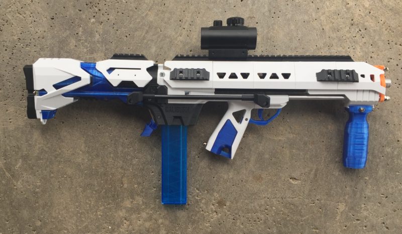
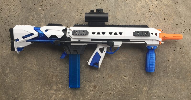
Version 0.2:

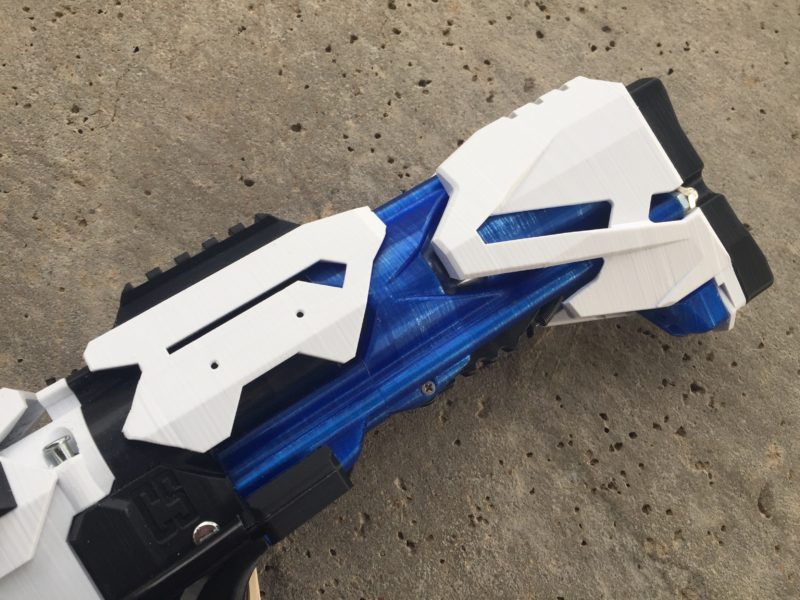
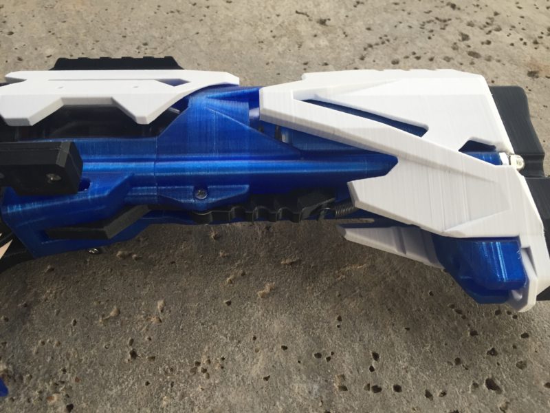
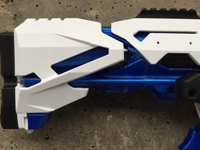
Note the reduced blue gap between the rear adjustable stock (white) and the plunger tube shroud (white). That is the main difference between 0.1 and 0.2 – the stock was reduced, and the modified Kiri, coupler housing and top rail were all merged together into one part.
And for comparison, here’s a shot of the bullpup and an official Caliburn Carbine:
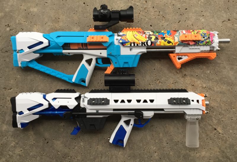
The current 0.2 version work is also focusing on expanding the thumbhole, moving the coupler bar inside the magwell, and adding a cosmetic piece to connect the grip to the magwell for a more traditional bullpup look.
In the spirit of trying to keep a summary of what this project is up to, here is a summary of the hardware modifications I made. I’ll update this as things change, but for now, here’s what I have done to the stock Caliburn hardware:
- Cut plunger tube to reduce length (final length TBD)
- Cut down rear threaded rods
- Increased length of front threaded rods by 1″. Need to work on the magwell to add captive screw ports to allow for stock threaded bars. (Note if you have a few of the older hardware kits with the longer top rods like I do, you can use them).
- Using two additional takedown pins
- Using an additional trigger spring
- Cut down K26 to 6″ (final length TBD)
- Used a few extra 4-40 screws (final count TBD)
Note the front threaded rods are longer than the stock rods. The original top rod was extended, and they work, but the newer magwells can work with all short rods. I had long rod lengths around and didn’t have to modify the magwell’s captive nut slots yet, but since I’m modifying the magwell anyway I’ll likely add captive slots up front to allow you to use all short rods. Most of the modifications I made were around cutting down stock parts which was acceptable to me.
Now on to the overly detailed narrative of the development process for this blaster! Thanks for reading!
Background
I have a collection of Nerf Caliburn blasters designed by Captain Slug. I’ve been building them for years, and wanted to tinker with modifying a design. I’ve outlined my detailed requirements and motivation below. This page summarizes my work from January through March of 2019 on this effort. The page is a pseudo-blog that contains a series of sections in the approximate order of the development of the blaster.
Disclosure – I just do this for fun. I’m by no means an expert in this field (e.g. Slug, MeakerVI, Kane, MrHeathPants just to name a few…), and with this project, I’m just tinkering because it’s an interesting combination of high performance toys, and data collection and analysis. I enjoy the statistical analysis side of the tuning process, and this hobby is rich in data collection and analysis opportunities. Hopefully you will see that combination in this project, as I get further into the tuning phase in the later stages.
At a high level, this is a basic modification of the base Caliburn to change the blaster layout into a bullpup design. This shortened the length of the overall blaster, while extending the grip forward to fit me more comfortably. There was an existing project that remixed the Caliburn into a bullpup (the Chimera linked below), but the design was not under active development, the hardware was difficult to source, and the assembly was complicated. I wanted a simple, cool looking bullpup to go plink solo cups with. So read on to see what I did!
Links of interest:
- Captain Slug: http://captainslug.com
- Nerf Caliburn: https://www.thingiverse.com/thing:2376150
- Slug’s other designs: https://www.thingiverse.com/captainslug/designs
- Captain Slug Etsy shop: https://www.etsy.com/shop/CaptainSlug
- Chimera project – first bullpup Caliburn (not maintained): https://www.thingiverse.com/thing:2976824
- The Taurus Bullpup Blaster (a nerf engineering marvel): https://www.reddit.com/r/Nerf/comments/9lfxt7/wip_homemade_bullpup_springer_taurus/
Requirements
I started investigating the build out of a Nerf Chimera bullpup, a 3D printed custom Nerf blaster that was heavily influenced and borrowed from the early design of the Nerf Caliburn by Captain Slug. After a few days of printing, roughing out the assembly and investigating the sourcing of hardware, I realized the project had several short comings (in my view):
- I thought the part count was high, and the complexity of assembly and tuning was time consuming when compare to the Caliburn.
- The required hardware components seemed to be intentionally different from the Caliburn. I preferred the approach of sharing as many parts as possible from both the existing Caliburn 3D printed designs and the hardware kits.
- I preferred the aesthetics of the Caliburn project, as well as some of the key new features like the breakdown magwells.
To that end I started roughing out what a Nerf bullpup Caliburn would look like, and what design modifications and hardware changes would be required to make this work. I went with a few key requirements:
- I wanted a compact design that shortened the Caliburn by a few inches.
- I wanted to preserve several key design aesthetics that I really like about the Caliburn, including:
- The Railgasm and RMAX2 barrel shroud
- The Stampede version of the adjustable stock
- The Caliburn grip
- I wanted to only use hardware pieces that Captain Slug used. This meant 10/32 and 4/40 screws, pins, threaded rods and nuts that he’s specified for the base kit. I didn’t limit myself to his part counts, but I kept the types of hardware in use the same.
- I wanted to keep the part count down to simplify assembly, and where possible, ensure that any asymmetrical design elements were reversible in case they impacted handed-ness requirements.
- I was not concerned with breaking 200 fps. This was envisioned as a 120 to 160 fps blaster used for sniping solo cups, and to simply look cool. Spring size and plunger tube dimensions could be compromised to achieve the look I was after. UPDATE: well the first design tests were hitting 190-200, so I’m already not too far off stock Caliburn velocities. Eventually I’ll drop the spring load down to get in my target ranges, but I think the platform may satisfy some of you that are looking to shoot your eye out.
So that was my starting point. This page walks you through the design and development of the remixed blaster, spanning updates from February 2019 through March 2019.
Initial Design
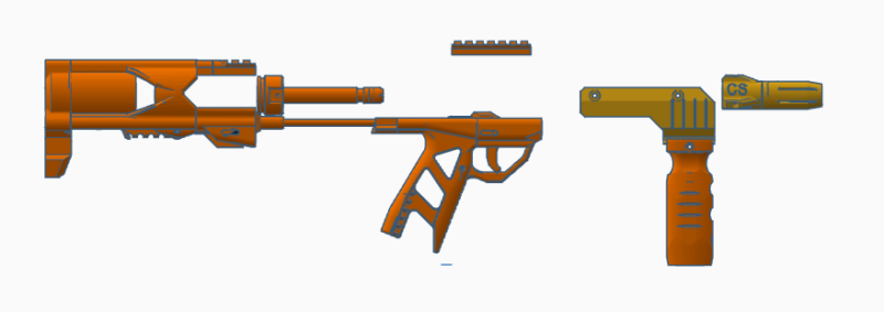
Initial prototype TinkerCAD work
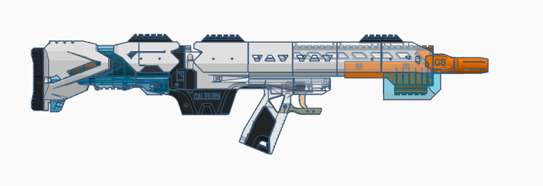
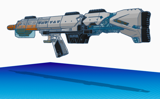
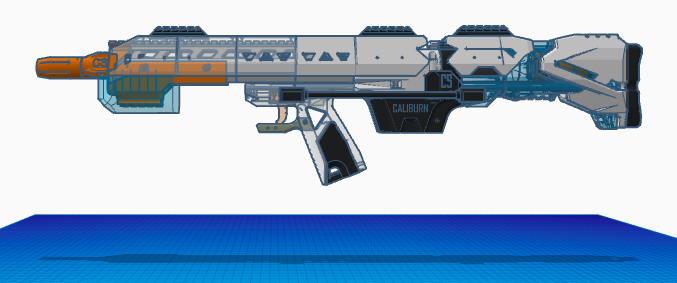
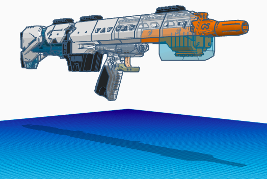
One of the early designs looked like this:
First printing impressions
The first time through the print required a few iterations on the:
- Kiri Stock replacement
- grip
- trigger
- trigger housing
- Priming shuttle
- rear RMAX2 shroud modification
I have the initial prototype printed, but I have to modify the sear coupler to improve the feel of the trigger pull. I was also printing a custom RMAX2 plunger tube shroud, and a mag release, stubby VF1, custom top rail extension, and rear rail are in the queue. So it’s getting there! In the meantime, I was experimenting with the current prototype:
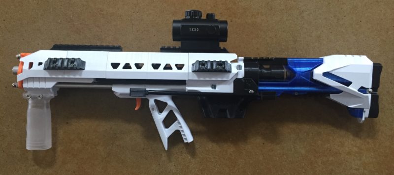
Here is an image of the blaster in the primed position:
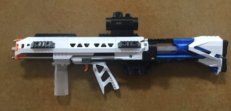
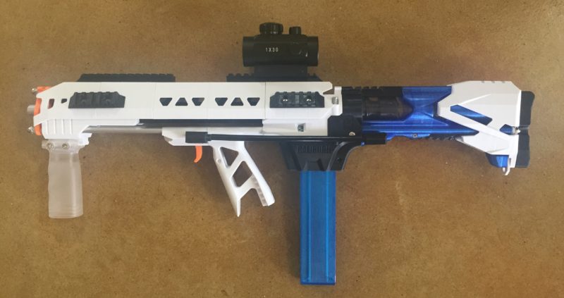
I did make a custom trigger guard, but given how short the blaster is and the 3.5 inch draw, the back of your hand would strike the trigger guard when primed. I ended up removing the prototype trigger guard and left the blaster as you see it.
I maintained the takedown magwell feature that Captain Slug designed. I really like this feature for swapping out springs quickly, as well as easier cleaning and tuning.
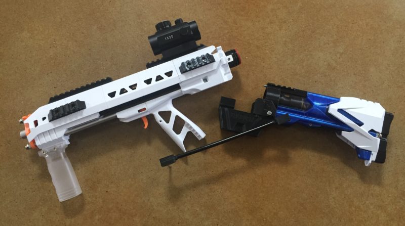
The backend of the blaster required some creative modifications. I wanted to shorten the plunger tube, but I wanted to maintain the styling of the Caliburn while using the RMAX2 shroud and adjustable stock. To achieve those goals, I had to pass the plunger tube through the Kiri Stock and create an opening further back in the blaster. This allowed me to use the adjustable stock while using the shorter plunger tube:
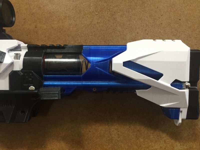
You also see a hint of the sear and trigger coupler. I’m using extra take down magwell pins that pass through a guide in the stock through the sear:
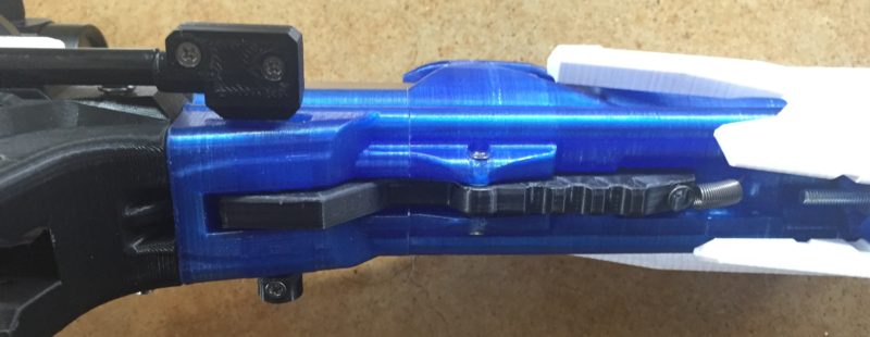
I moved a spring to the back of the sear to ensure it engages properly. This was the easiest way I could think of to reduce the part count. This initial clamshell design was a bit flimsy, so I’m trying another prototype that will hopefully be a little more rigid. This design is OK and works, but it is a bit “wiggly”.
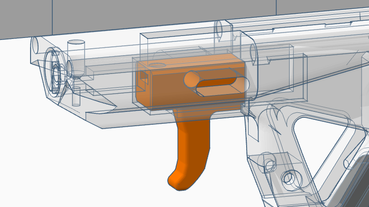
Here is a cutout view of the sear and the coupler:
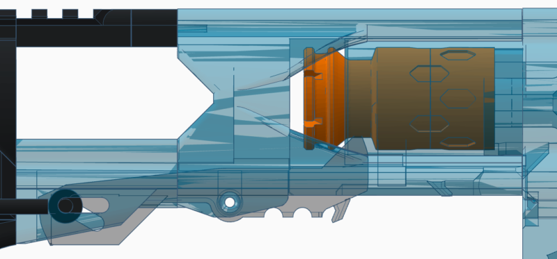
The coupler has a horizontal slot for a pass through pin. The sear has an angled slot that pushes the front of the sear up as the trigger is pulled, forcing the rear of the sear down, releasing the plunger.
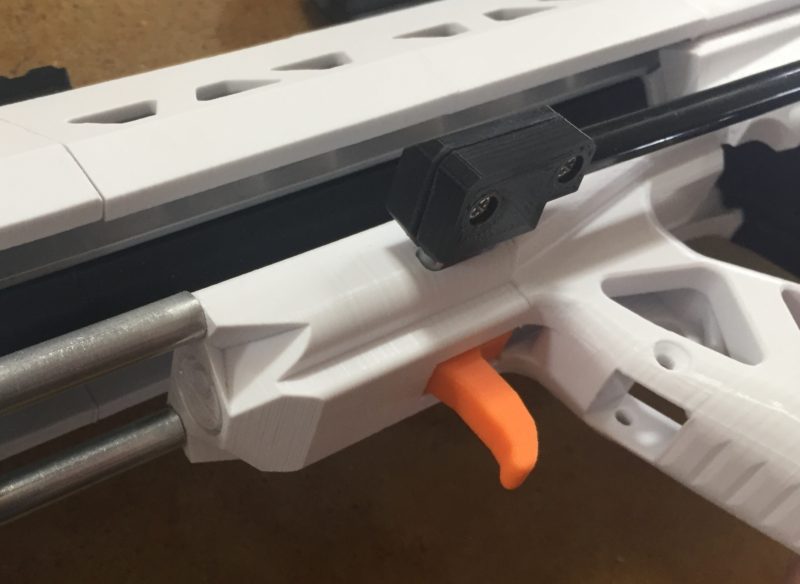
Similarly the trigger uses another take down pin. I designed a trigger housing that has a return spring in the front of the trigger, with a slot in the grip that allows the trigger block to slide backward pushing the coupler bar back, tripping the sear:
Here’s a dry firing demo – eek! But the sound was cool, and I wasn’t sure if it would actually work lol:
Intermediate photos
After the initial prototype testing I printed out a few more pieces. You can see the addition of a blue glass grip insert and matching mag release. I also printed out a custom rear RMAX2 plunger tube shroud. And of course a stubby VF1 fluted stabilizer 🙂
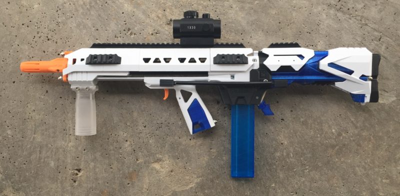
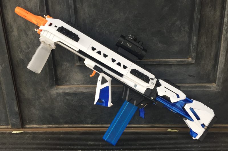
There are still a few more parts to print:
- Reprint of the grip (there was some weird artifact in the first stl).
- Reprint of the priming shuttle, centering the picatinny rail.
- Coupler bar iterations.
- New trigger guard design.
- Considering designing my own fore grip so I can print it in blue glass to keep the design theme going.
Refining the sear / trigger couplers
Probably the most complicated parts in my design were the smallest – the couplers used to connect the trigger to a threaded rod to the sear. Given that I didn’t want to customize Captain Slug’s shortened carbine magwell, I wanted to connect the trigger and sear via an external threaded rod that would not interfere with the breakdown mag feature. I couldn’t think of a way to pass the rod through the grip and magwell while still allowing for simple breakdown, so I went with the idea of using extra breakdown magwell pins coupled to the threaded rods with a custom printed part.
My first design used a clam shell approach where the pin head was nested inside the plastic piece along with a captive nut port for the threaded rod. The clamshell was bound together with two 4-40 screws. This design was pretty compact, but I had a hard time keeping the pin from wobbling.
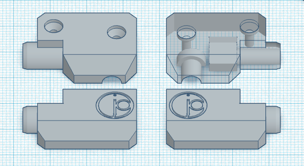
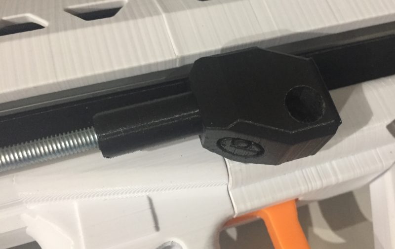
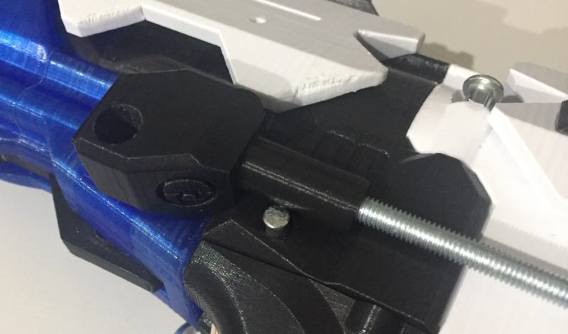
My next design idea borrowed from Slug’s idea of just friction fitting the pins in a tight hole that you might need to bore open with a drill bit. This yielded a much more stable pin retention, and eliminated the need for the 4-40 pins since the new design was a solid block:
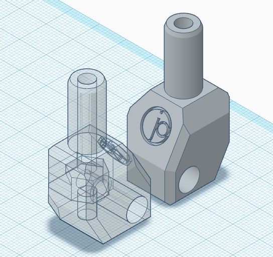
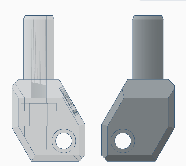
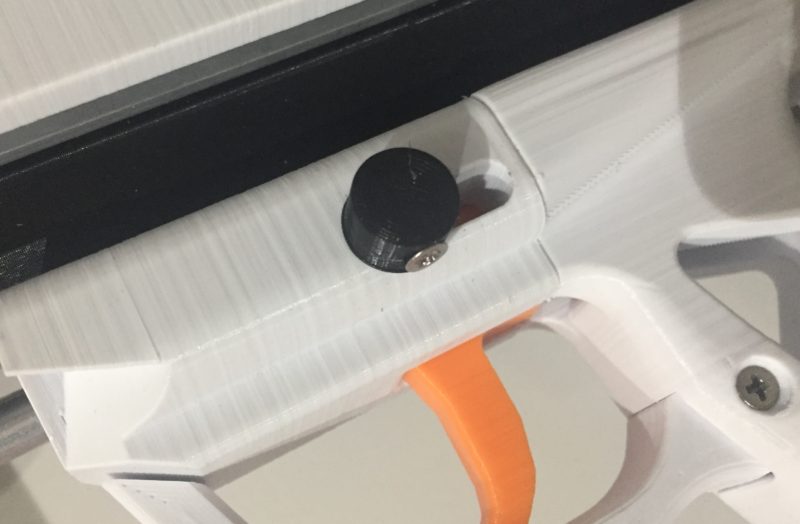
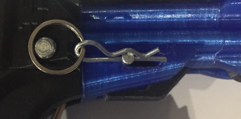
This coupler design is the first component that will likely stray from Slug’s parts list. I’d like to be able to quickly remove the rod for servicing the spring or plunger tube, and to do that I don’t want to insert a 4-40 screw into a bored out hole on the coupler pin. I am using two cotter pins on the opposite side of the coupler for now, but I do have some nicer looking pin caps that will house a 4-40 screw for a more permanent connection. I may use one of those on the trigger housing an a cotter pin on the back which should allow for the breakdown functionality while maintaining a cleaner look up front.
Here are close up images of the couplers:
Here’s a short video on the trigger assembly:
Initial chronograph results
I’m using a six inch section of 9662K31, a spring that has very similar performance characteristics to a K26. This particular spring comes in 36″ lengths, so it’s more useful for experimenting with different spring lengths.
All Nerf-like darts used in these experiments are half-length Worker darts which are considered to be amongst the most accurate after-market Nerf-dart-alternatives available. You can find alternative darts that may clock in at higher velocities, but these are real-world velocities with darts that would be used in typical Nerf applications (we mostly just plink solo cups).
The first chronograph checks were:
- 192
- 191
- 190
- 190
- 187
- 199
- 189
- 186
- 195
- 200
From a performance perspective, the blaster is exceeding my initial design hopes. We’re using a 3.5″ draw, a 6″ spring length, and a smaller plunger volume than the Caliburn. Overall I am happy with the state of the blaster.
I do need to improve the catch, as some trigger pulls are not releasing the plunger. I have more debugging to do there.
Full Chronograph session #1
Welp the coupler prototype failed part way through the chronograph session :). This was my fault as I left the threaded rod exposed while waiting for carbon fiber tubing to arrive. Since the tubing was missing, the rod was not under tension and backed itself out of the screw in the rear coupler housing. I ended up finishing the session because I had the mags loaded, but the standard deviation on this session is higher than it should be. I’ll rerun this once I lock down the final design, but I figured I’d post the data since I had it. Additionally this gives you some insight into the iterative nature of the design and test cycles associated with the project.
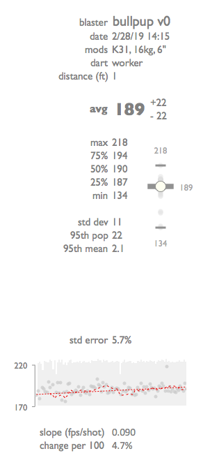
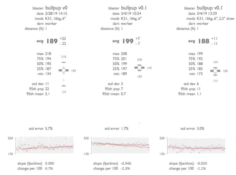
The full session yielded an average for 100 shots of 189 fps, with a standard deviation of 11, with an approximate 95th percentile of 22 fps, so we are seeing 189 +/- 22 fps. I had some trouble with the coupler during the initial phase of the chronograph session, and you can see some relatively low velocity shots in the initial portion of the session. The slope of the population increased over time, illustrating how I was able to correct for the coupler issues as the session went on.
I’ll rerun this test after I finish my coupler refinements, along with a few other revisions. Overall, this was a solid first bench session.
Coupler finishing touches
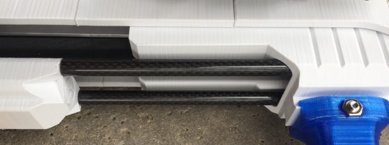
As I mentioned above, the coupler was missing the outer tubing that provides the tension to ensure the coupler assembly maintains rigidity. I was going to use stock aluminum tubing, but I thought this build deserved something fancy, so I ordered some carbon fiber tubes. After cutting to length, the coupler now looks like this:

The addition of this length of tube allowed me to put enough tension on the captive nuts to maintain the integrity of the coupler under heavy use. I’ll get to another chronograph session after one more update to the grip (more on this below).
While I was at it I replaced the front aluminum tubes with carbon fiber as well:
Custom front grip
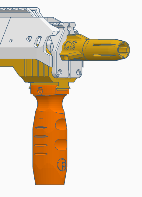
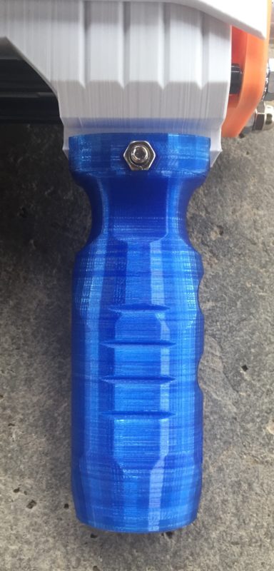
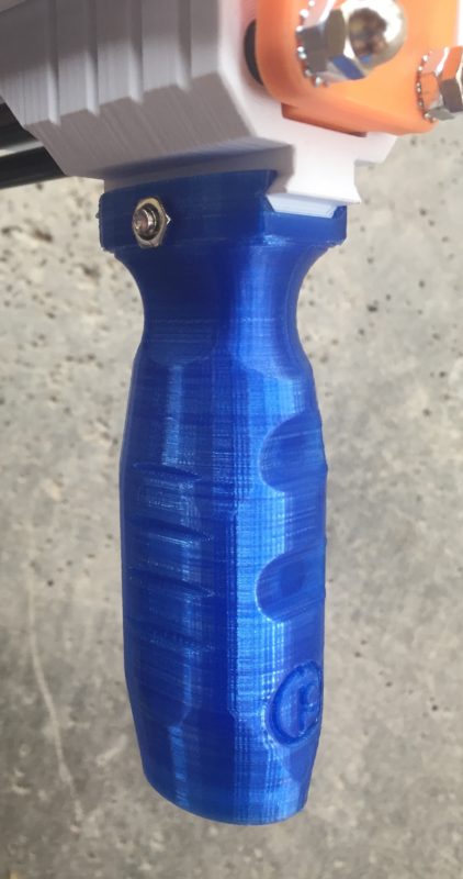
The worker grip I was using on the prototype was comfortable, but I wanted a custom look to the front of the blaster that matched the color scheme (blue glass!). I started working up my own design that fit my hand and was narrow enough to fit within the draw of the blaster, so I came up with this (after a few iterations):
Images of the printed vertical grip:
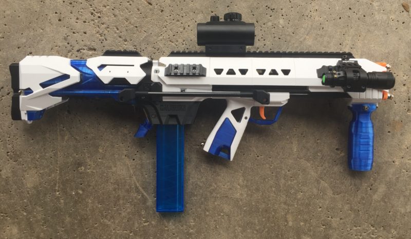
Here is an updated shot of the Caliburn bullpup blaster:
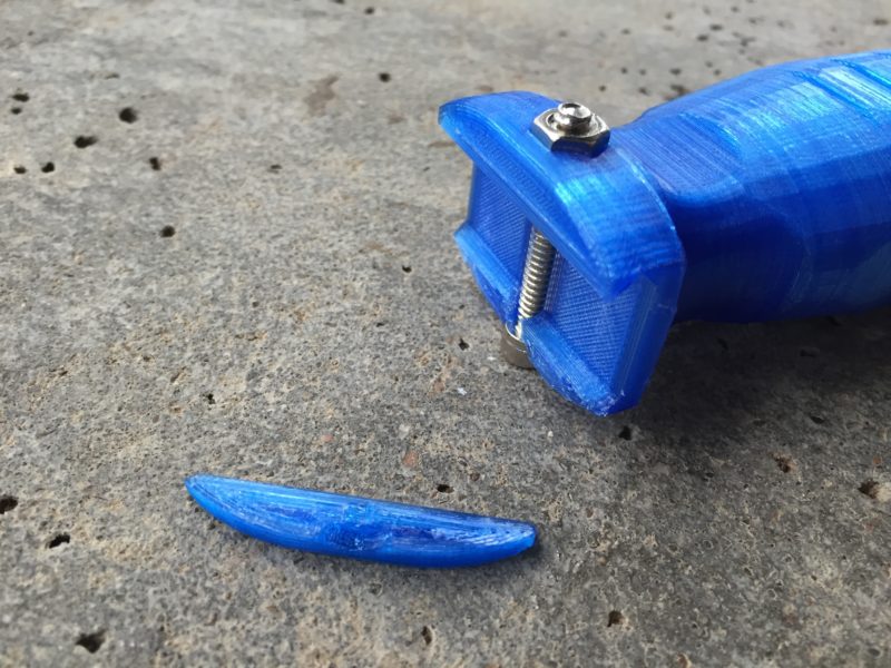
Update: So I snapped this fore grip lol. It was on me, as I was debugging the sear with the blaster in the upside-down position holding on to the bottom of the grip against the full force of the 16kg spring watching the catch as I moved the plunger back and forth, then CRACK!
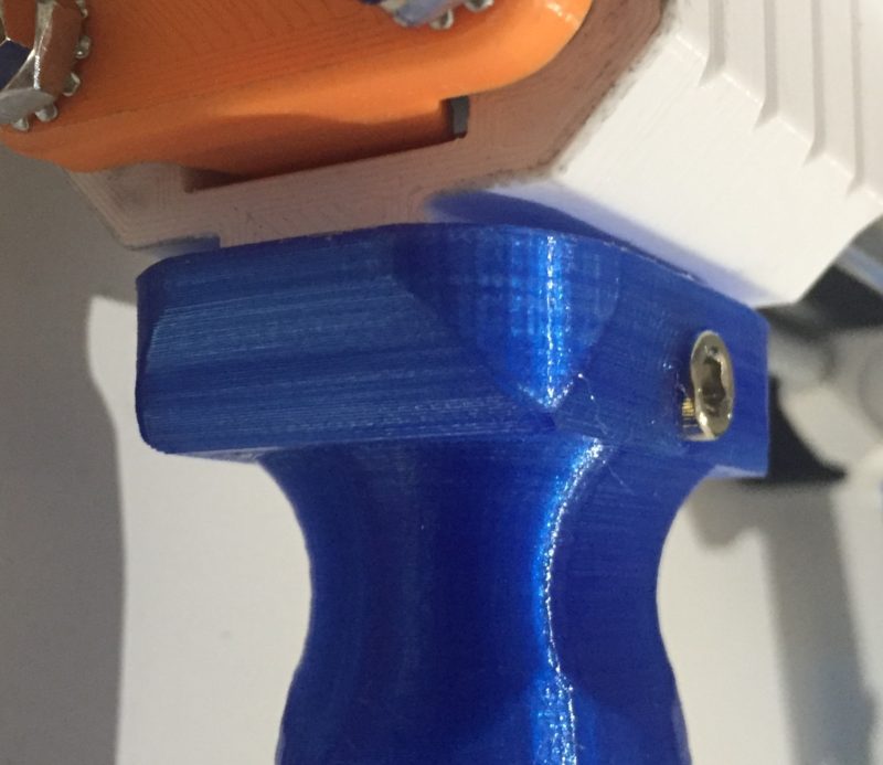
I went ahead and redesigned the top of the grip, closing off the front of the picatinny slot which will likely limit the use of this grip on other blasters. I also significantly thickened the picatinny mount point. You can use whatever fore grip you want on the front priming sled, I just wanted something custom for this platform that looked cool and that you could print to match your color scheme, so I was good with giving up compatibility on other platforms to strengthen the grip.
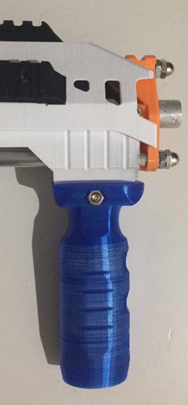
You can see where I connected the front of the picatinny mounts to strengthen the grip:
And here it is from the back:
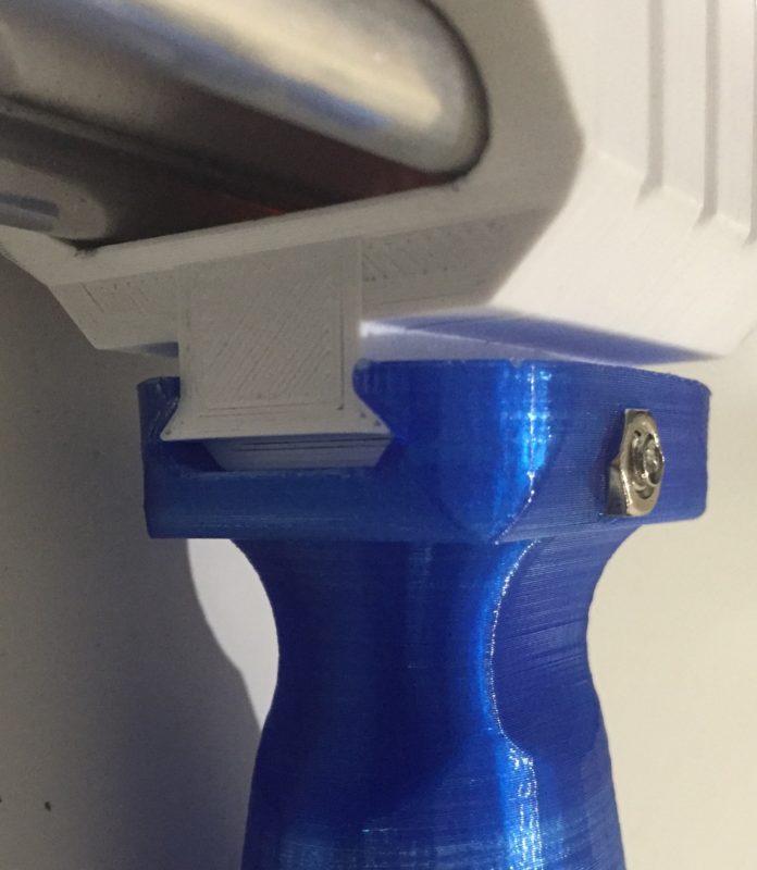
So the grip now slots in, and cannot be slid back beyond the front of the sled. We’ll see how this design holds up!
Trigger guard iterations
You can see in the prior image that I have been iterating through trigger guard designs. I have little room in this nerf bullpup design for the 3.5″ draw. My thumb strikes the trigger guard in this design, so I’ve been iteratively reducing it while ensuring the trigger pull and index finger placement is still comfortable.
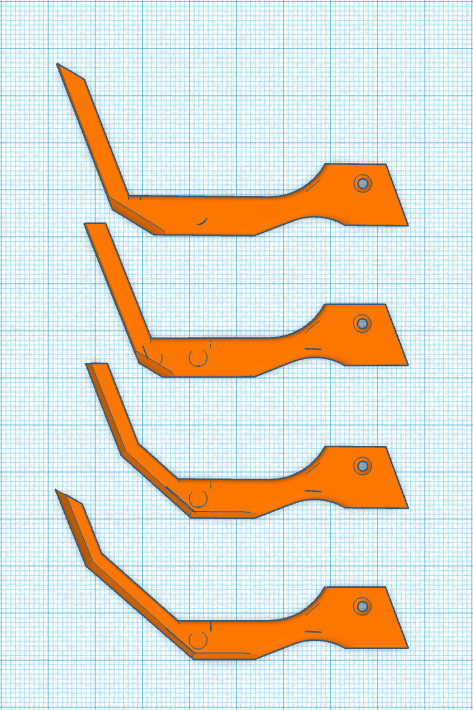
From top to bottom, I’m shifting the front of the trigger guard back, and with the current iteration at the bottom, angling the front to make room for my thumb during a prime. The fourth revision pushed the top back out to the original position, but angled the front more.
We’ll see if I can slowly get there. I’ve been removing the trigger guard during most sustained use like chronograph sessions.
Check back for updates!
Update: I was happy with the fourth version. I am thinking about designing a knuckleguard that arcs back under the grip and connects to the magwell. It might fit better with the bullpup look. Hopefully the iterations on the trigger guard weren’t wasted.
Grip revision
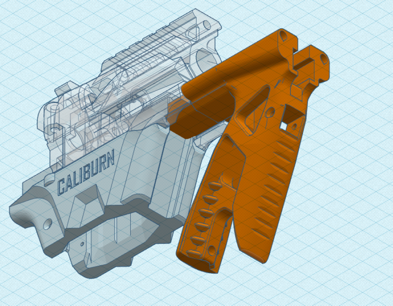
I noticed during the first chronograph session that there was some rocking of the grip as I was priming at a faster rate. The initial prototype just had the grip in front of the magwell and held in place through tension within the threaded rods. I decided to revise the grip to include a slotted rear segment that fit into the breakdown magwell slot. This should add stability to the design during heavy use:
Version 0.1 Complete!
Some final revisions include the trigger guard and grip revisions outlined above. I also switched back to aluminum tubing on the front threaded rails. The carbon fiber flexed more than I liked and the prime seemed sloppier with them. I’ll see if I can further tighten up the grip / magwell coupling, but I’d prefer to leave the magwell as is rather than mess with it. Anyhow here is a picture of the first complete working version of the blaster:
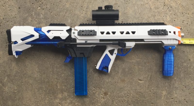
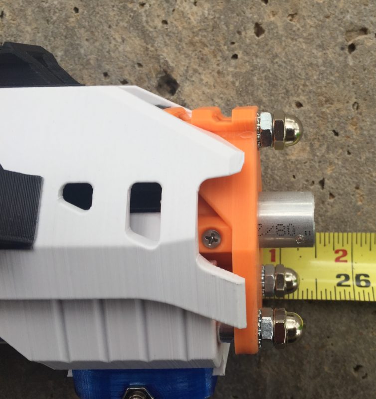
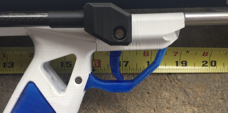
Key characteristics:
- 25.5″ overall length (does not include fluted stabilizer)
- 14″ barrel
- 3.5″ prime draw
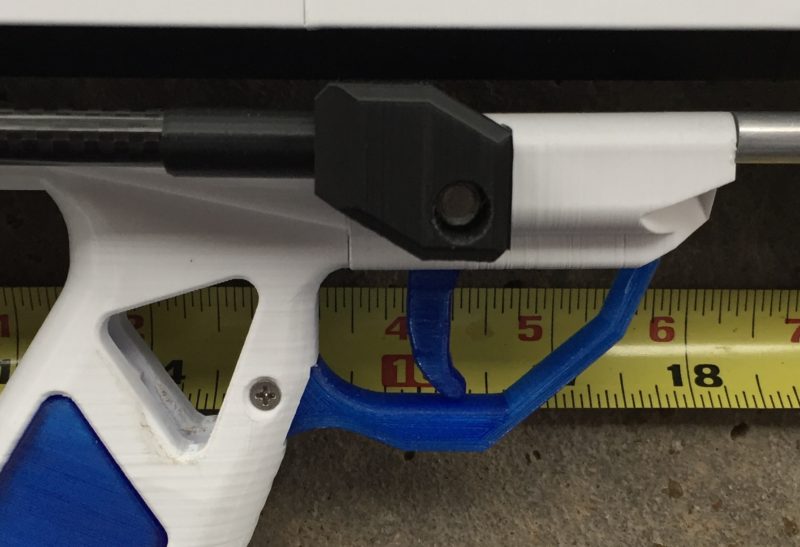
- 16.5″ length of pull (midpoint of butt to trigger)
Open questions:
- Is the length of pull too long? For comparison, a Tavor bullpup’s LOP is 15 3/4 – a bit shorter, but seems reasonably similar to me.
- Can the draw be further reduced? The prime is currently 3.5″
- If the draw is reduced, can the length of the stock be reduced as well?
Tuning
Chronograph session #2
After making final changes to the trigger, adding the coupler tubing, and stabilizing the grip, I ran a second chronograph session to see how the stability of the platform changed. If you recall from above, we were working with a fairly high initial standard deviation of 11 fps, with an average and 95th percentile confidence interval of 189 +/- 22 fps. So here we go!
The 0.1 version of the blaster hit 199 +/- 7 fps, with a standard deviation of 3.5 fps for a population of 100 shots! This was much better than I expected, with a very low standard error rate, meaning the fps rates were extremely consistent throughout the chronograph session.
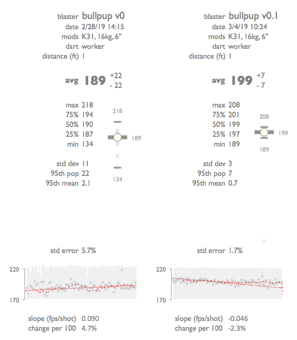
I know that graphic is pretty long, but man look at that box plot spread before and after!
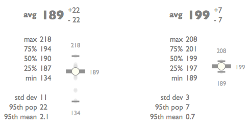
That was a great crony session 🙂 It’s not that the peak performance of the blaster improved (note the greater max on the first session compared to the second) but rather the range tightened up and became far more predictable. The minimum rate rose from 134 to 189.
Draw reduction experiment
The draw length on the initial design was approximately 3.5 inches – about the same length as the Chimera bullpup Caliburn revision, and about the same draw as the Caliburn Carbine front end released by Captain Slug. After Slug saw my initial design, he commented that the draw length looked long. That got me thinking about stealing another one of Slug’s ideas for a quick experiment to see the impact of a reduced draw on top-end fps. I lengthened the back of the RAM, and the front of the plunger. This added about 3/4″ of dead space and a reduced draw.
I added 10mm (and another o-ring slot) to the RAM and 11.5mm (and another o-ring slot) to the plunger. In all that is 21.5mm of reduced draw. I figured I’d experiment with compensating for the reduced draw with additional o-rings to see if I could improve the air seal while reducing draw.
You can see the original prototypes in white, and the elongated revision with the additional o-ring slots in orange:
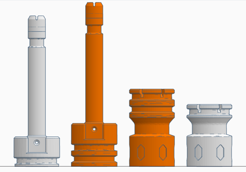
The intent here was to create an experimental RAM/Plunger set that reduced the draw. If I see decent fps out of this, I may rework the backend of the blaster to further reduce the plunger tube size / stock length.
Here’s a look at the change in prime distance on the front of the blaster. The starting unprimed state:

Full 3.5″ draw:

Reduced draw (less 21.5mm) of ~2.7″

Chronograph session #3
The third session with a reduced draw to 2.5″ came in at 188 +/- 11 fps. This was a decent result, with a minimal drop in fps for the 21.5mm decrease in prime length.
I’ll likely work on another stock / kiri variant that shaves 3/4″ off the back end. I like the idea of the double o-ring option too, so I may tweak the RAM and plunger as well. I’ll have to run some experiments with this setup and the extra o-rings removed to confirm though.
Version 0.2: 20mm length reduction
My goal with this experiment was to get the Length of Pull (LOP) down closer to the 15.75″ LOP of the Tavor bullpup. Based on my quick searching around, the consensus was this LOP was designed for 5.5 to 6 feet tall people. I’m over 6 feet, so the current LOP is pretty comfortable to me, but I understand the concern. I also ensured backward compatibility with Slug’s adjustable stock, so if I shorten the blaster, I can compensate with the adjustable stock.
Given the results we saw above with a rapid test shortening the prime length to simulate a reduction in the length of pull, I went ahead and designed a new combination Kiri stock (shortened by 20mm), top rail, and sear housing since the overall length fell below 155mm, or the height of my build volume.
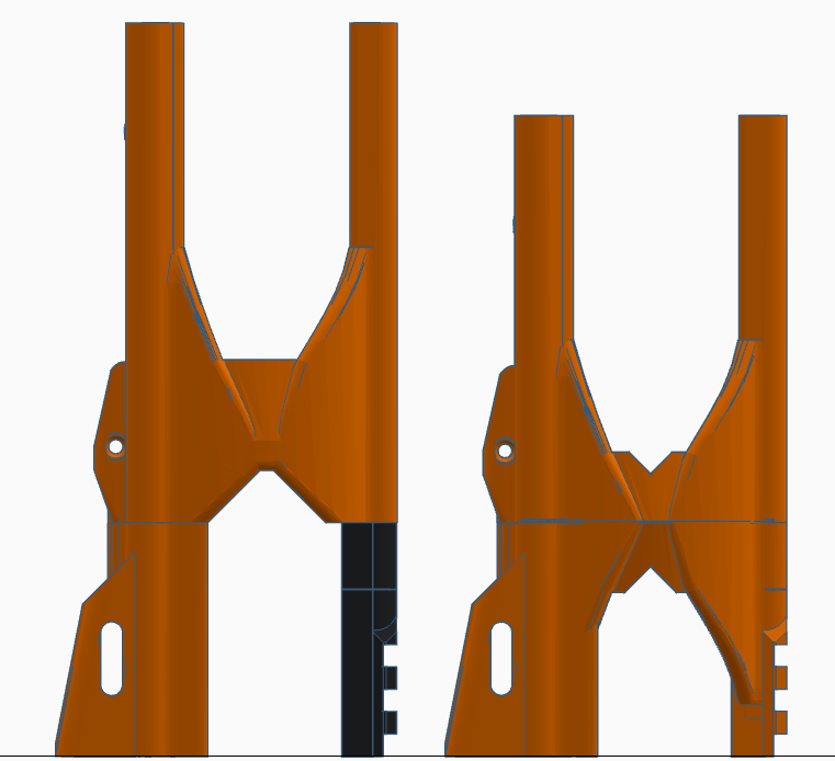
This has further shortened the plunger tube volume, but a target of 190 fps is still well within my original design specification. I know this part is relatively large from a build volume and time perspective, but I do like the reduction in parts, and added sturdiness having a fused set of parts.
Along with the reduced size of the stock, I had to reduce the length of the sear. It’s comically small now compared to the original Caliburn, so we’ll see if this impacts the trigger pull substantially.
Here’s a look of the bull pup next to a Caliburn with a carbine front end. Both have stock 14″ barrels installed:

Here’s a look at the reduced area on the stock:
And the current LOP:
The total length:
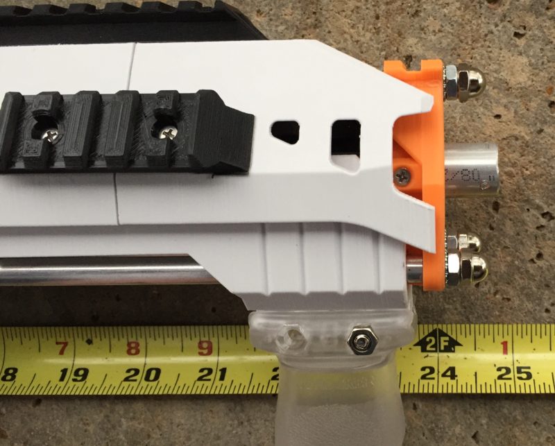
The Wet Cat
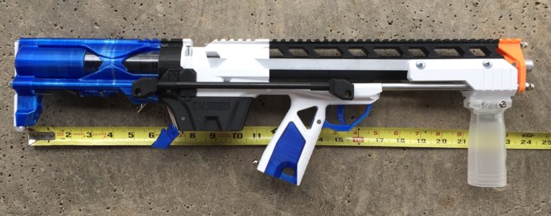
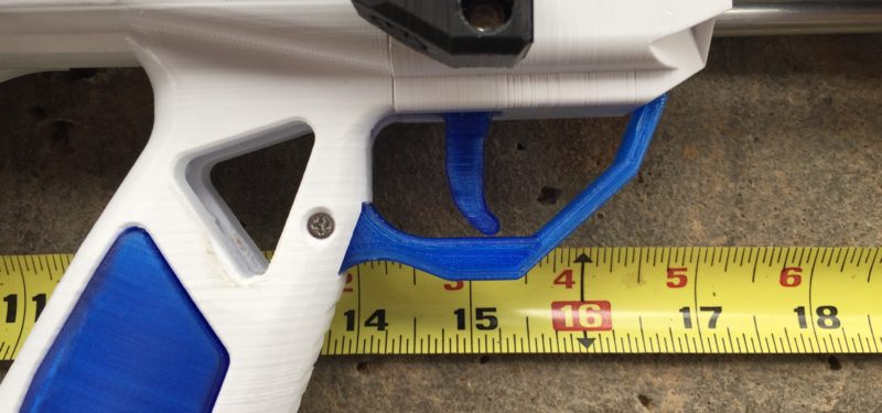
MeakerVI asked to see the blaster without the shrouds and accessories. I removed the RMAX2 kit and adjustable stock. I laughed at how tiny the blaster was, and thought it looked like a wet cat without it’s shroud:
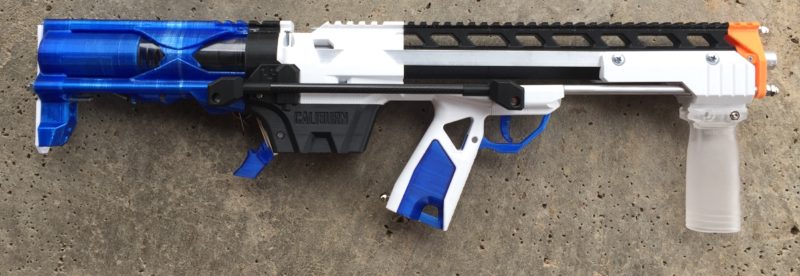
The angle is playing some tricks on you visually, but when you line up the tape measure to the butt of the stock, we’re now just a hair under 24″:
The length of pull is about 15 inches without the adjustable stock:
And the 14″ barrel is just at 24″:
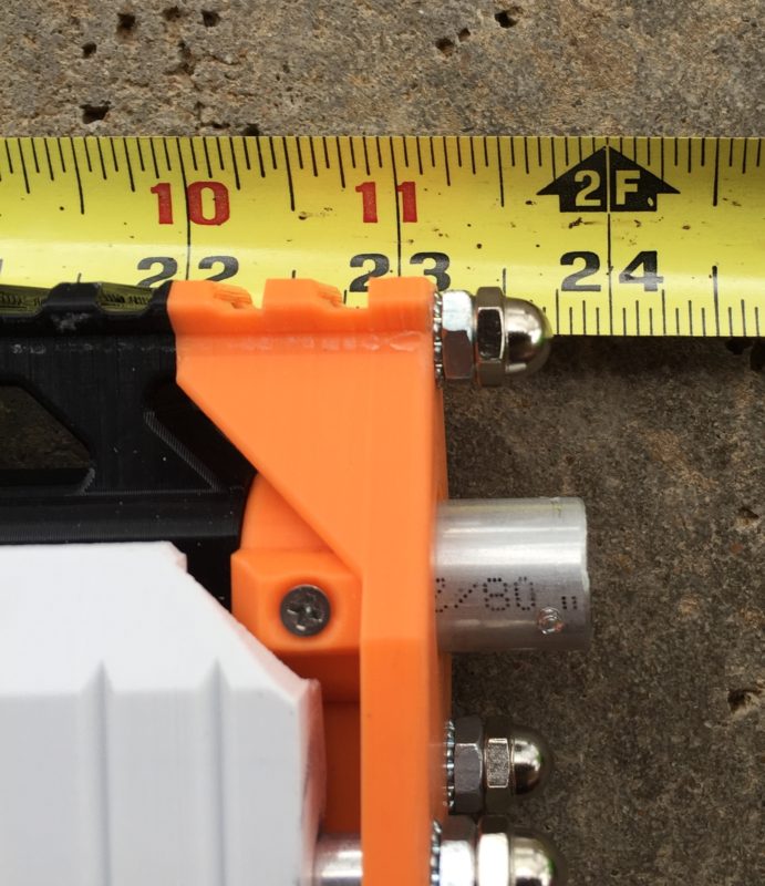
The wet cat joke got me thinking, maybe this project name should be Mr. Goodkat.
Chronograph session #4
This session focused on profiling the 20mm reduction in the stock length. I found the prime harder, as we’re compressing the 6″ spring in a more restricted space. I also managed to snap two vertical grips priming the 16kg spring. I’ll probably have to shorten the 16kg spring, or switch to an angled fore grip. I also partially profiled a 10kg to get an idea of how a stock long shot spring would do.
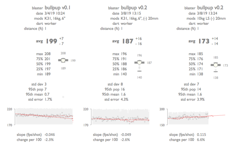
This plot shows the v0.1 profile of 199 +/- 7 fps on the left. The center column is the same spring in the v0.2 version that was shortened by 20mm. The difficult prime and erratic plunger behavior led to more varied results. The abridged longshot 10kg run shows a trend upwards, but some work will be required to refine the trigger pull and plunger in this configuration. I suspect the plunger may be rubbing on the back of the stock.
EDIT: after inspecting the blaster, I noticed I was missing a screw at the sear pivot. This happened to me before, and was usually the cause of the low FPS shots. I’ll likely have to re-profile, but I’ll probably save that for the magwell revisions.
Overall, the Longshot spring is good enough for my purposes. I think I may switch down to that spring for future profiling, or possibly both.
Version 0.3: trigger internalization
I was going to include the magwell work in version 0.2 (since these are internal development versions right now, and nothing public), but the rework was pretty extensive, so I decided to capture a snapshot of the blaster STL’s with the reduced stock and then edit away on the magwell in case I wanted to revert to 0.2 if my redesign ideas were a complete and utter failure.
This iteration is focused on:
- internalization of the coupler bars. I’m adding a second to even out the force applied to the coupler and hopefully make the trigger less mushy.
- Elimination of the takedown pin requirements by using two threaded rods directly attached to the trigger and sear coupler.
- Switch to a 4/40 coupling nut as the pivot for the sear, in place of the rear takedown pin.
- Complete internalization of the sear coupler.
- Punching holes through the upper magwell and Milan Coupler (eeeekkk!!! – a potentially big failure point).
- Reducing the front magwell upper and lower to increase room for your thumb.
- Design a cosmetic part that connects the grip and the magwell. Consider a knuckle guard as part of the design. Purely cosmetic, but I’m including it here since I’m working on the magwell.
The downside of this work is I have to mess with the magwell. I am deadset against giving up the takedown compatibility, so I’m going to have to put some thought into how I attach the threaded rods to the trigger and sear to make internal decoupling possible.
I’m really concerned about punching a set of holes through the Milan Coupler, as that has been a known weak point in the Caliburn design, but I couldn’t see a feasible way of putting two rods through the lower magwell and making the blaster look right.
Sear coupler revisions
The first step I took in internalizing the coupler was to focus on the sear end. I had very little room to work with. I wanted to maintain the takedown functionality, so I had to come up with a strategy for handling the decoupling of the coupler. I didn’t want the user to have to unthread the coupler, so I started with a concept of threading the trigger end and having the threaded rods push on the sear end. I didn’t have enough room to use an extension spring, so I broke my requirement (!!!) to only use Slug’s official parts and picked up some assorted compression springs and used two of them to assist in the return of the sear couplers to their starting position.
The key modifications were:
- Elimination of the use of a takedown pin. They were too long to internalize fully.
- Use of a 4-40 stand off to improve the pull action against the sear wedge.
- Use of two coupler bars, one on each side of the blaster.
- Use of two 4-40 screws to bind the coupler to the sear. The new design is much more stable, and should better handle a 16kg spring.
- Use of two compression springs to assist in coupler return.
Here was the first revision (note the springs are not to scale):
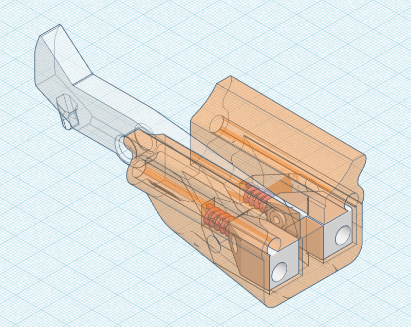
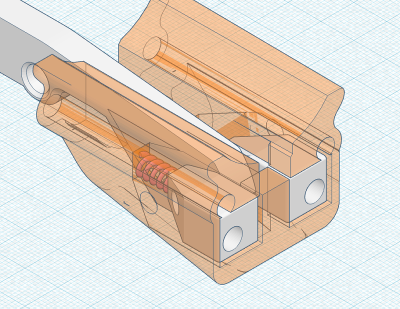
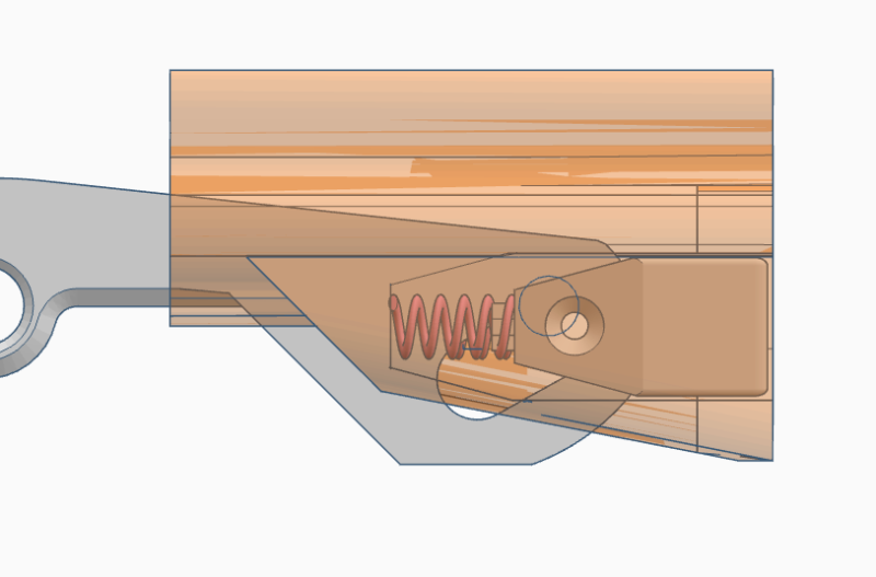
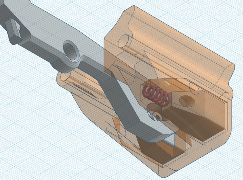
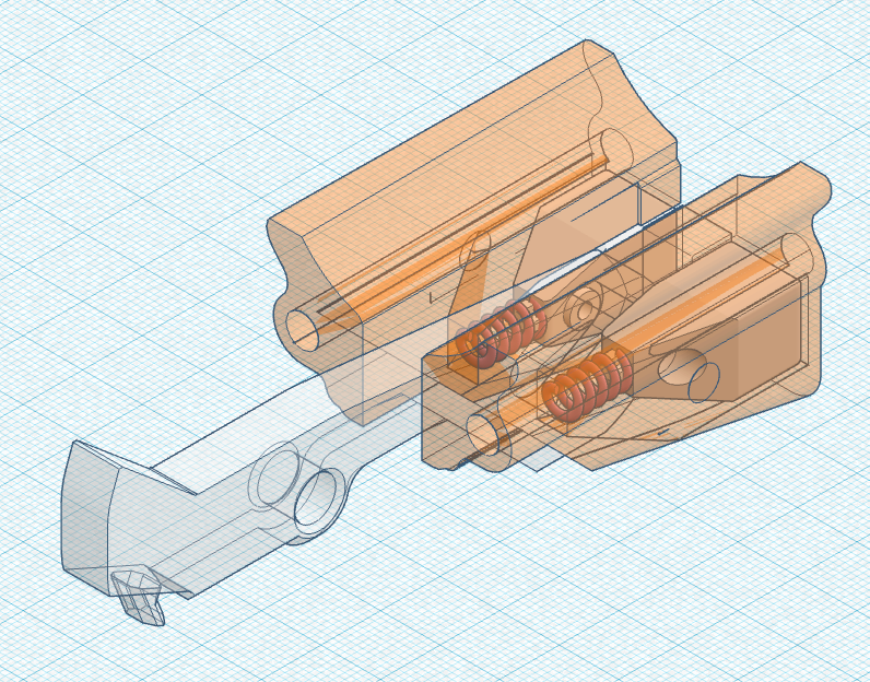
I had trouble with thin walls on this version, and I didn’t have an easy way to assemble it. Another revision was in order! I focused on slimming down the couplers to increase the wall thickness of the coupler housing. I also eliminated some of the bracing on the Milan Coupler end allowing for an assembled sear coupling to be slid into the coupler housing. The sear pivot standoff should hold the sear in place.
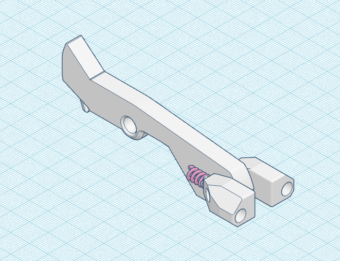
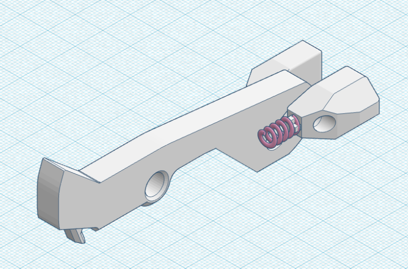
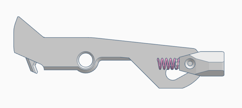
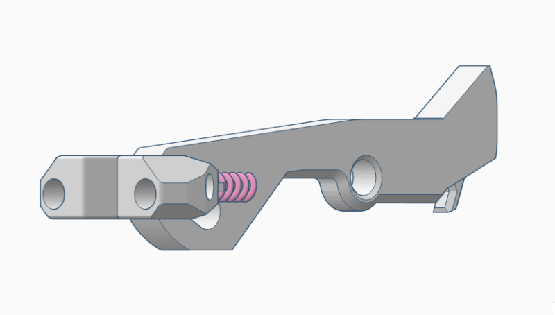
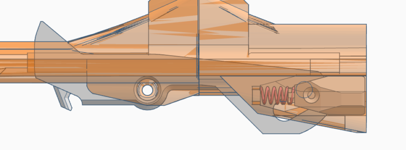
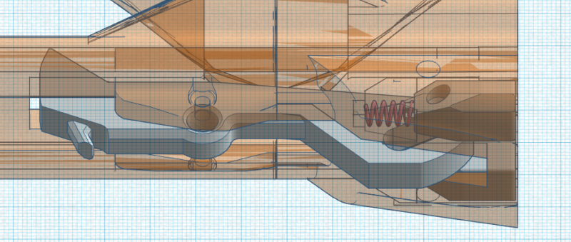
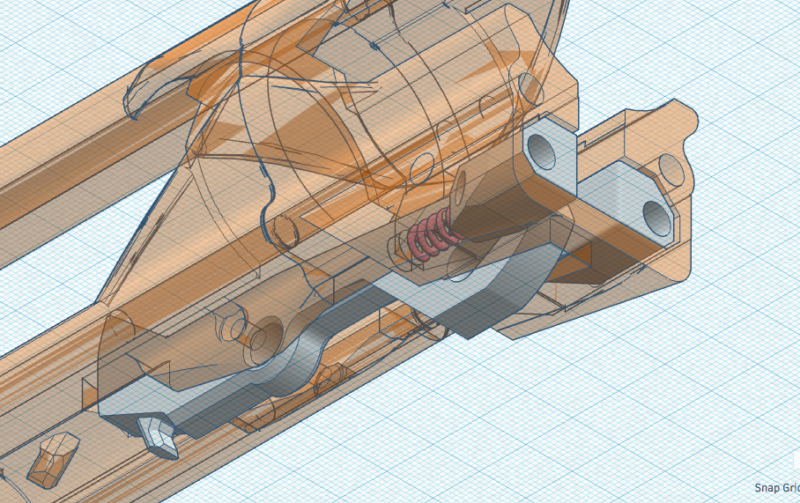
I left the extension spring pegs on the back of the sear and stock in case I need the extension spring as well to ensure the sear engages properly. You’ll notice the rear coupler threaded rod wells are about 6mm, which will allow the rods to seat freely within the coupler. This should allow me to set the depth of the rods on the trigger end, and have them seat quickly within the coupler during magwell takedowns. In theory it seems cool and like it will work, but we’ll see how this goes in practice.
The second revision prototype is printing. Check back soon for more updates!
Magwell revisions
In the queue…
Grip revisions
In the queue…
Trigger & trigger housing revisions
In the queue…
Hardware kit mods
I have this section as a placeholder for now. Once the project gets to a stable state, I’ll put together a list of instructions on how to assemble a bullpup blaster with Captain Slug’s hardware kit, and what additional parts you’ll need to source (outside of, well, printing this thing haha).
